Introduction to Diode:A diode is an electrical component that only allows one path of electricity to flow while restricting the other. Despite the existence of other diode technologies, the semi-conductor diode is the most common type of diode used in modern circuit design. Historically, the word "diode" has been reserved for small signal appliances, I 1 A. When a diode is used in a straightforward battery light circuit, the diode will either allow or prevent current flow through the lamp, depending on the polarization of the supplied voltage. Although there are many different types of diodes, they all serve the same basic purpose. The silicon diode, which is housed in a glass cylinder, is the most common type of diode.
The symbol of diode is represented as follows:
Diode Operation:
When a voltage signal is applied across the terminals of a diode, the diode begins to operate. Biasing is the process of applying a DC volt to a diode to initiate operation in a circuit. Since a diode is like a one-way switch, it may operate in either the conduction or non-conduction modes. Forward biasing, which simply means applying a greater or positive potential to the anode and a lower or negative potential to the cathode of a diode, results in the "ON" mode of the diode. Reverse biasing, which simply means that higher or positive potential is put on the cathode and on the anode, allows a diode to operate in the "OFF" mode, whereas a diode operates in the "ON" mode when negative or lower potential is supplied.
The practical diode offers forward resistance when the switch is "ON." Cut-in-voltage is the forward bias voltage required by a diode to enter the "ON" state. While breakdown voltage, which occurs when reverse bias voltage exceeds its limit, causes the diode to start conducting in a reverse biased way. When there is no voltage applied across the diode, it is in the OFF state.
Function of Diode
The primary job of a diode is to allow electricity to flow in one direction while blocking it in another. Forward current is the current that flows through the diode, whereas reverse current is the current that the diode blocks.
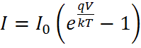
Diode Equation:
The current flow through a diode is expressed as a function of voltage in the diode equation. The optimal diode formula is..
- I – Stands for the net current passing through a diode.
- I0 - Stands for dark saturation current, the diode seepage current density in the deficiency of Ligh
- V – Stands for applied voltage across the terminals of the diode
- q – Stands for fixed value of electron charge
- k – Stands for Boltzmann’s constant
- T – Stands for fixed temperature (K)
Here we are assuming that diode is ideal, this is just for the purpose of discussion.
1. When diode is in ON mode, no voltage is there across it; hence it acts like a short circuit.
2. Whereas when diode is in OFF mode, there is zero current, hence it behaves like an open circuit.
3. From the above two conditions, either one can take place at a time. This helps us to check out what will happen in any
circuit with diodes.
Diode Characteristics
Diodes have attributes that allow them to carry out a number of electronic functions. Three vital characteristics of diodes are
as follows:
- Forward Voltage Drop- forward bias about seven volts.
- Reverse Voltage Drop- Weakened layer broadens, generally the applied voltage.
- Reverse breakdown voltage- reverse voltage drop that’ll force flow of current and in maximum cases demolish the
diodes.
Types of Diodes
Small Current Diode
Large Signal or Large Current Diodes
Zener Diodes
LED (Light Emitting Diodes)
Photodiodes
Constant Current Diodes
Schottky Diode
Shockley Diode
Step Recovery Diodes
Tunnel Diodes
Varactor Diodes
PIN Diodes
LASER Diode
Transient Voltage Suppression Diodes
Gold Doped Diodes
Super Barrier Diodes
Point Contact Diodes
Peltier Diodes
Gunn Diode
Vacuum Diodes
Avalanche Diode
Crystal Diode
Zener Diode
The breakdown voltage of a Zener diode is precisely controlled by regulating the doping level during manufacturing. Zener diodes are a unique kind of device created to function in the Zener breakdown area (reverse breakdown zone). Diode Zener Low reverse voltages cause Zener failure if the diode is strongly doped. On the other side, Zener breakdown happens at high reverse voltages if the diode is just weakly doped. Zener voltages for Zener diodes range from 1.8 volts to 400 volts.
The Zener diode has a higher doping level than a typical p-n junction diode. As a result, the depletion region is exceedingly narrow. Because of this, it permits higher electric current than typical p-n junction diodes.
Similar to a regular diode, a Zener diode permits electric current to flow in the forward direction, but it also permits electric current to flow in the reverse direction if the applied reverse voltage is higher than the Zener voltage. Because it was created to operate under reverse bias, it is thus constantly linked in the other direction.
Zener diodes are the fundamental components of electronic circuits and are utilized in a variety of electronic devices to prevent overvoltage in electronic circuits.
symbol of Zener diode
The symbol of Zener diode is shows in figure. it consists of two terminals: cathode and anode. in Zener diode, electric current flows from both anode to cathode and cathode to anode. the symbol of Zener diode similar to the normal p-n junction diode, but with bend edges on the vertical bar.
LED (Light Emitting Diodes)
What is LED (Light Emitting Diode)?
- The Light emitting diode is a two-lead semiconductor light source.
- In 1962, Nick Holonyak has come up with an idea of light emitting diode, and he was
working for the General Electric company.
- The LED is a special type of diode, and they have similar electrical characteristics of a PN
junction diode. Hence the LED allows the flow of current in the forward direction and
blocks the current in the reverse direction.
- The LED occupies the small area which is less than the 1 mm2. The applications of LEDs
used to make various electrical and electronic projects.
- The light emitting diode is a p-n junction diode. It is a specially doped diode and made up
of a special type of semiconductors. When the light emits in the forward biased, then it is
called as a light emitting diode.
How does the LED work?
- The light emitting diode simply, we know as a diode.
- When the diode is forward biased, then the electrons & holes are moving fast across the
junction and they are combining constantly, removing one another out.
- Soon after the electrons are moving from the n-type to the p-type silicon, it combines
with the holes, and then it disappears.
- Hence it makes the complete atom & more stable and it gives the little burst of energy in
the form of a tiny packet or photon of light.
- From the diagram, we can observe that the N-type silicon is in red color, and it contains
the electrons, they are indicated by the black circles.
- The P- type silicon is in the blue color, and it contains holes, they are indicated by the
white circles.
- The power supply across the p-n junction makes the diode forward biased and pushing
the electrons from n-type to p-type. Pushing the holes in the opposite direction.
- Electron and holes at the junction are combined.
- The photons are given off as the electrons and holes are recombined.


Comments
Post a Comment